Anton's hardware experience: Electronics/EDA
This is a selection of the more-complete hardware projects that I've designed and built:
- 2023: GFMPW-1 group ASIC submission
- 2023: raybox-zero ASIC/FPGA design
- 2023: Various other VLSI/ASIC tapeouts
- 2023 and earlier: Various PCB designs
- 2020: CPLD breakout board and experiments
- 2019: NES STM32 dynamic code loader
- 2018: ESP8266 'IKEA cubes light painter'
- 2017: ESP8266 non-OS SDK YouTube video
- 2014: Label printer hacking
- 2012: PIC MCU-based PAL video generator
- 2012: USB audio device
- 2012: Stereo microphone preamp
- 2011: Home PCB etching
- 2003: 8051 MCU-based 'computer'
- 2002: Flash ROM reader/writer device
¶2023: GFMPW-1 group ASIC submission
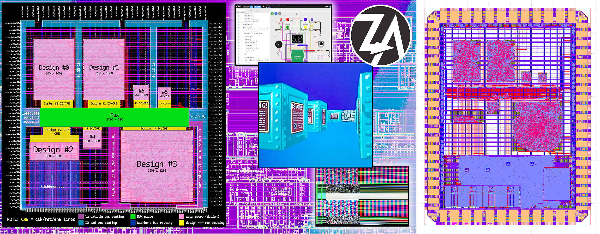
This is a group ASIC shuttle submission that I managed for some designs of my own, plus 3 other contributors.
See:
- GitHub repo
algofoogle-multi-caravel - Efabless repo
ztoa-team-group-caravelas submitted to GFMPW-1.
When I started learning ASIC design, the Google Open MPW program had just gone into hiatus. The last (?) Google-sponsored shuttle was later announced as GFMPW-1 (on the GF180 process node, i.e. Global Foundries 180nm).
I helped 3 other people join my submission to GFMPW-1. This included designing a mux (to share GPIO pads) and overall layout, helping with hardening, writing doco and example firmware to show how to control the mux, automated testing with Cocotb, and managing the overall group and submission process.
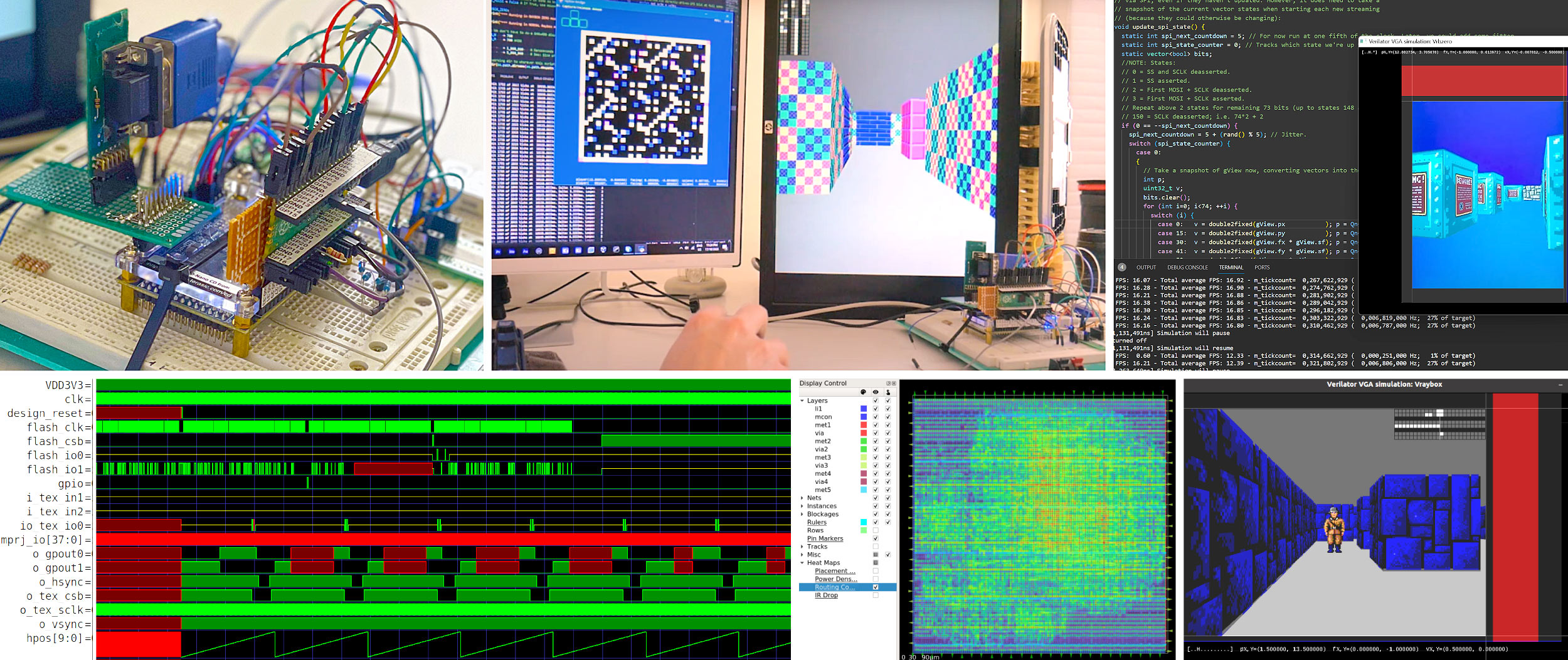
¶2023: raybox-zero ASIC/FPGA design
This was my first substantial ASIC design submission to an Efabless shuttle, as part of Tiny Tapeout 04 (TT04).
See:
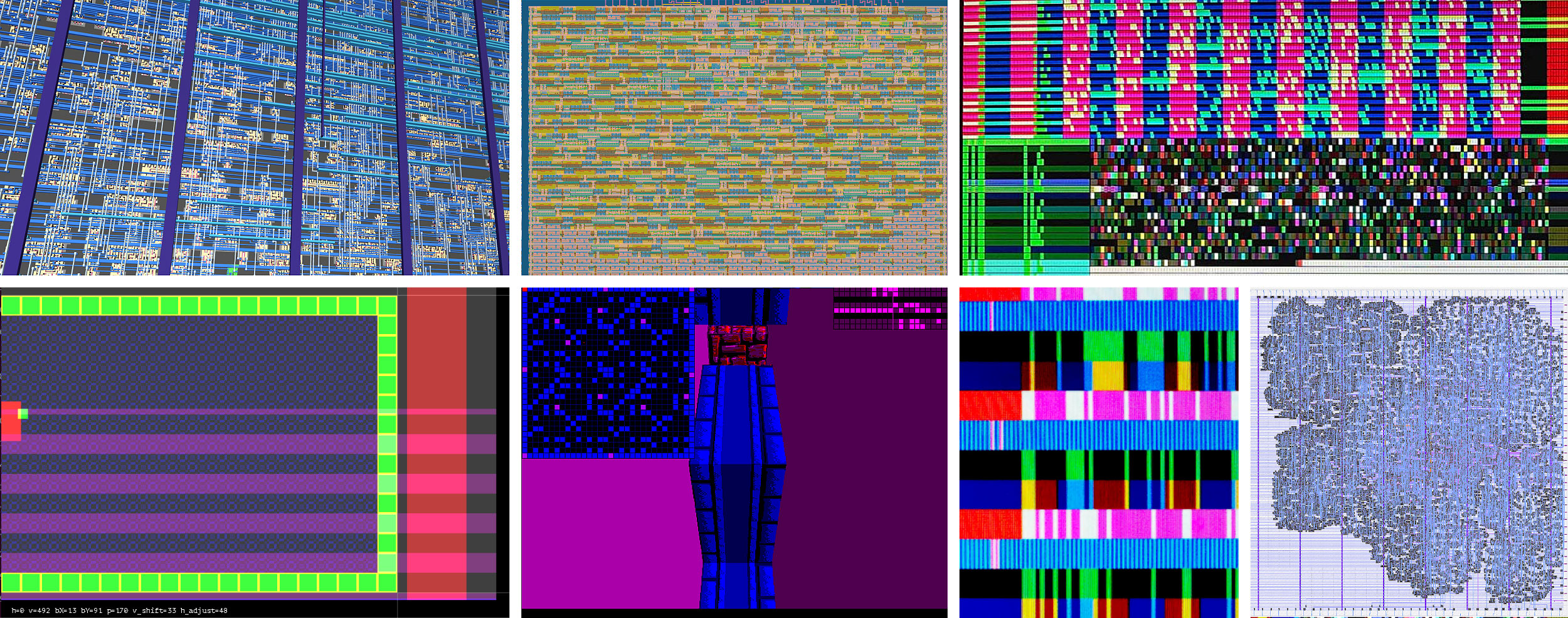
The design is a 'ray caster' implementation in Verilog which drives a VGA display and creates the illusion of moving around a 3D world. It 'races the beam', i.e. does all calculations and draws the display in real-time, 60 frames-per-second, without a framebuffer.
I developed and tested this in multiple ways:
- Verilator, for near-realtime simulation on a PC.
- Cocotb, for thorough RTL and gate-level automated tests.
- Running it on a real FPGA (DE0-Nano board, i.e. Altera Cyclone IV) with hardware peripherals plugged in.
Features:
- 640x480 (VGA) resolution at 60fps with 6-bit (RGB222) colour.
- 64x64 texture mapping for 8 distinct textures (4 wall types, 2 'shades' each) from external SPI memory.
- Double-buffered 'point-of-view' vectors that can be updated by an external SPI controller.
- Other double-buffered registers that can be updated on a separate SPI interface, to alter rendering behaviours.
- Optional debug overlays, and registered and unregistered output options.
To help verify the SPI interfaces and create a meaningful demo I also wrote Raspberry Pi Pico firmware and a Python 'bridge' that runs on a host PC to send test data and live keyboard/mouse interactions to the design. This works by sending the 'game state' and other test data serially over USB to the Pi Pico, which then bit-bangs the SPI interfaces and other control signals of the design on the FPGA.
¶2023: Various other VLSI/ASIC tapeouts
I've been involved in 5 tape-outs so far that have been accepted for fabrication. Besides submitting to TT04 (raybox-zero) I've so far also taped out designs on:
- TT03: Simple clocked multiplier. My first tapeout.
- TT03p5: I submitted a simple VGA game to an experimental Tiny Tapeout shuttle. The design is called 'solo_squash' and it resembles 'Pong'.
- TT05: vga_spi_rom: Experiment to test positive and negative clocks with OpenLane, and visualising latency on a VGA display, by implementing a QSPI reader design.
- CI2311: I was lucky enough to submit a version of raybox-zero on a private chipIgnite shuttle, allowing me larger area than my original TT04 submission, and tweaking other parameters such as pin placement. I collaborated with two others to bring our designs together on the same die and share available Caravel resources without a mux. As a result, this became an exercise in doing a considerably more pin-constrained version of raybox-zero, with many internal functions managed via the Caravel Logic Analyzer and firmware instead of external pins.
I've also made documentation and code contributions to some parts of the stack in both Tiny Tapeout and the Zero to ASIC course.
¶2023 and earlier: Various PCB designs
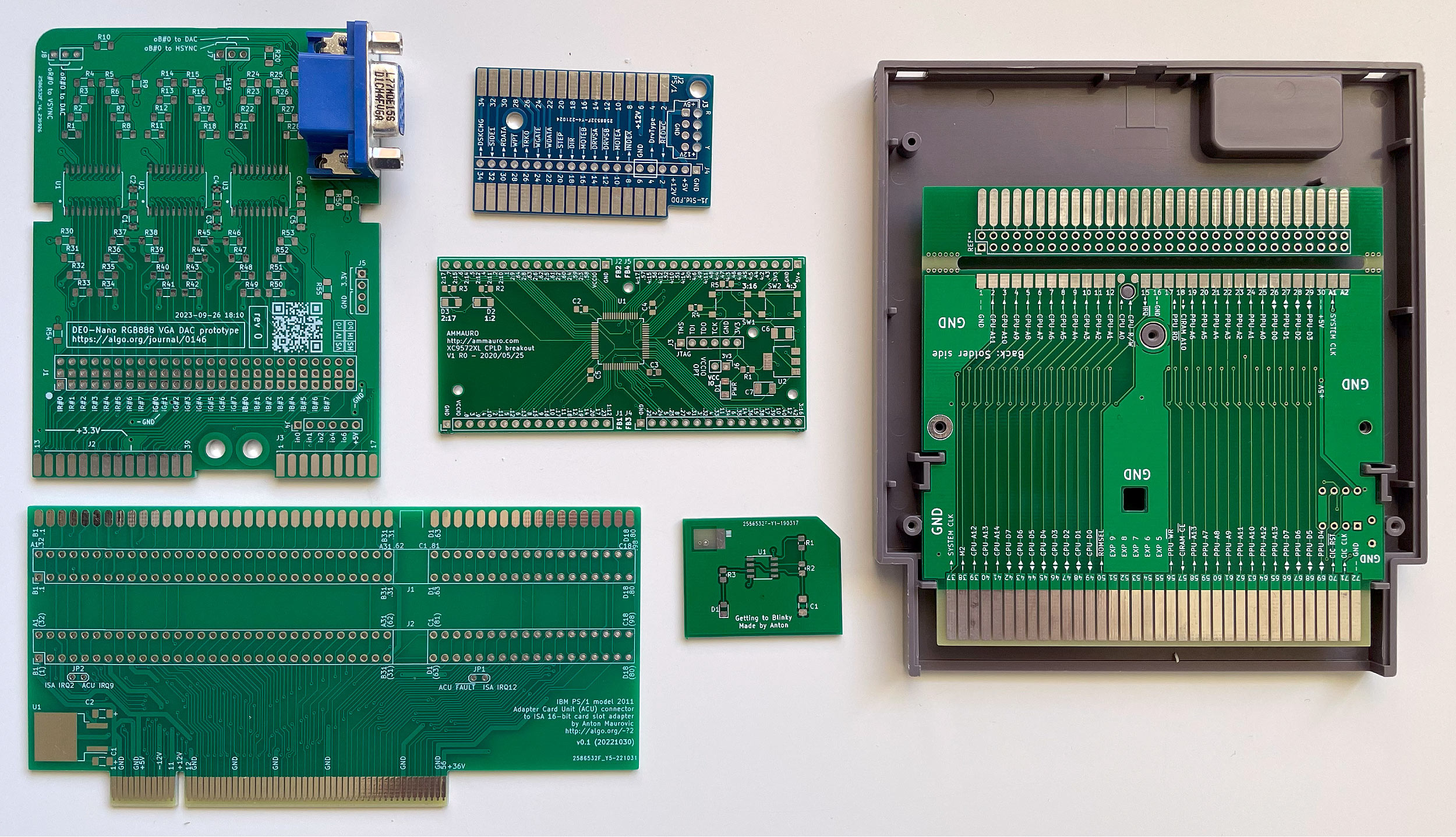
These are some examples of PCBs I've designed in KiCad and had manufactured by JLC PCB in China.
I typically write scripts to help with parametrically generating both the schematic symbols and footprints. In several of these examples, my approach was to define the larger arrays of pins and edge connectors in a spreadsheet (including detailed info for silkscreens) and then convert them into KiCad library files.
In the middle is my XC9572XL CPLD prototyping board (see below) for more info.
Besides that, clockwise from the right we have:
- Precision-matched NES cartridge adapter/dev board (see below for how I used this).
- A tiny test board (my first).
- IBM PS/1 'ACU' (Adapter Card Unit) bridge prototype (to hopefully feature later in a YouTube video series I'm working on).
- 24-bit VGA RGB DAC prototype.
- IBM PS/1 to standard FDD adapter (for part of the same video series mentioned above).
¶2020: CPLD breakout board and experiments
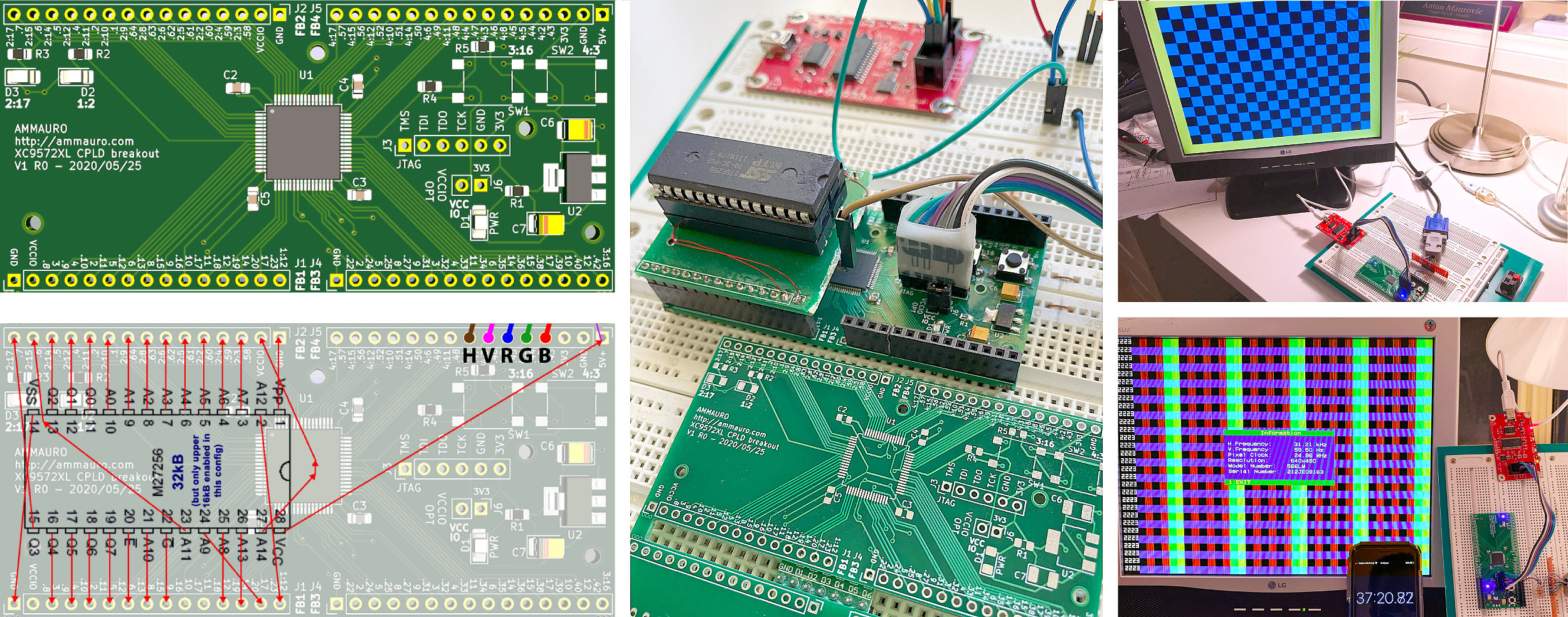
This is a board I designed and made that allowed me to experiment with a particular Xilinx CPLD.
See: My journal entry about making this board
I started experimenting with Verilog and wanted to use the Xilinx XC9572XL CPLD to interface with some older hardware (because of its 5V-tolerant pins). I designed a simple breakout/development board and hand-soldered it. This was my first time soldering a TQFP so I was pleasantly surprised when it worked on the first try.
I synthesised some simple designs using the Xilinx ISE WebPACK, and used a modified Bus Pirate 3.5 for JTAG.
My favourite projects revolved around driving a VGA display, including a simple game which later became the basis of my TT03p5 'solo_squash' submission.
¶2019: NES STM32 dynamic code loader
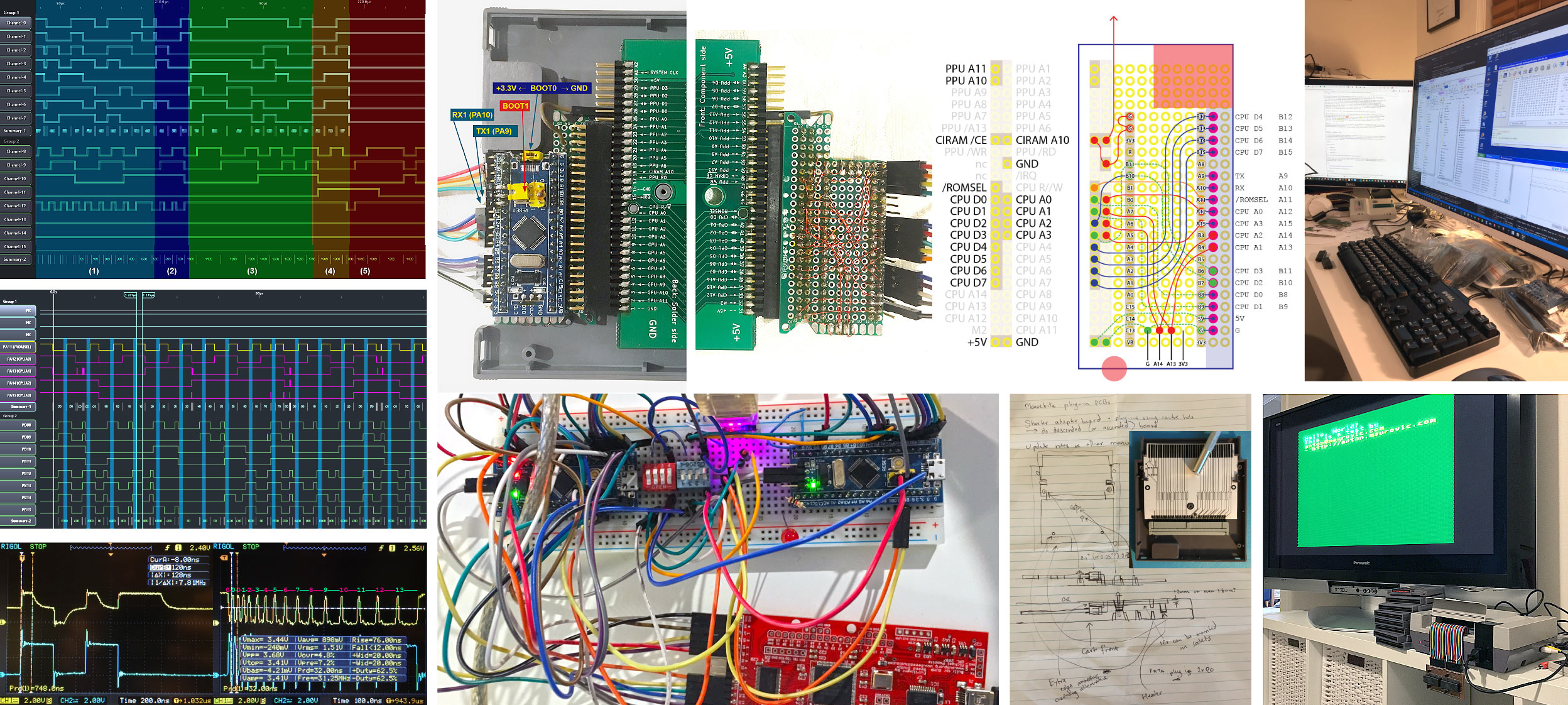
This project was an attempt to put wifi capabilities into a 1980s Nintendo Entertainment System cartridge, that then became an experiment and learning experience on multiple fronts to dynamically inject NES code via an STM32 in real-time.
See:
- STM32 bare-metal implementation and hardware interfacing (May 2019 to August 2019)
- Initial NES development (up until May 2019)
- Original design goals
This was probably the most-involved project I had worked on prior to getting into ASIC design. I used what was a VERY affordable STM32F103 'Blue Pill' board to develop a sort of dynamic code delivery system for making a NES (Nintendo Entertainment System) development cartridge. The STM32F103 is one of only a few such devices with 5V-tolerant pins but the problem is that it has far fewer than the NES needs. I designed a solution that could live-feed code and data to the NES in real time, using a sort of dynamic NES 'bootloader'.
The first trick is that the bootloader executes within only the upper 8 bytes of the NES address space. The NES CPU is made to loop through those 8 addresses, each time getting different instructions fed to it by the STM32 which keeps track of states internally. Once the main bootloading is done, it is able to load a larger program and graphics data into the 2kB of internal NES RAM. Finally, that program is then able to stream additional data from the STM32 (and optionally via its own USART) using memory-mapped IO but with a more-formal protocol.
Because the NES CPU runs according to its own clock and doesn't support wait states, it was necessary to make the STM32 able to sample the NES CPU bus fast enough (and respond fast enough), and this required:
- Careful analysis of the NES cartridge port bus timing and quirks
- Overclocking the STM32
- Bare-metal ARM assembly coding to get very tight timing control
- Automated hardware-level testing: I used a 2nd STM32 to simulate the NES bus, and prove over a series of tests and over a long period of time that the first STM32 was responding correctly and quickly enough.
I partially implemented an interface between the STM32 and an ESP8266 to add wifi capabilities to the cartridge, but moved on to other projects during the COVID19 pandemic.
¶2018: ESP8266 'IKEA cubes light painter'
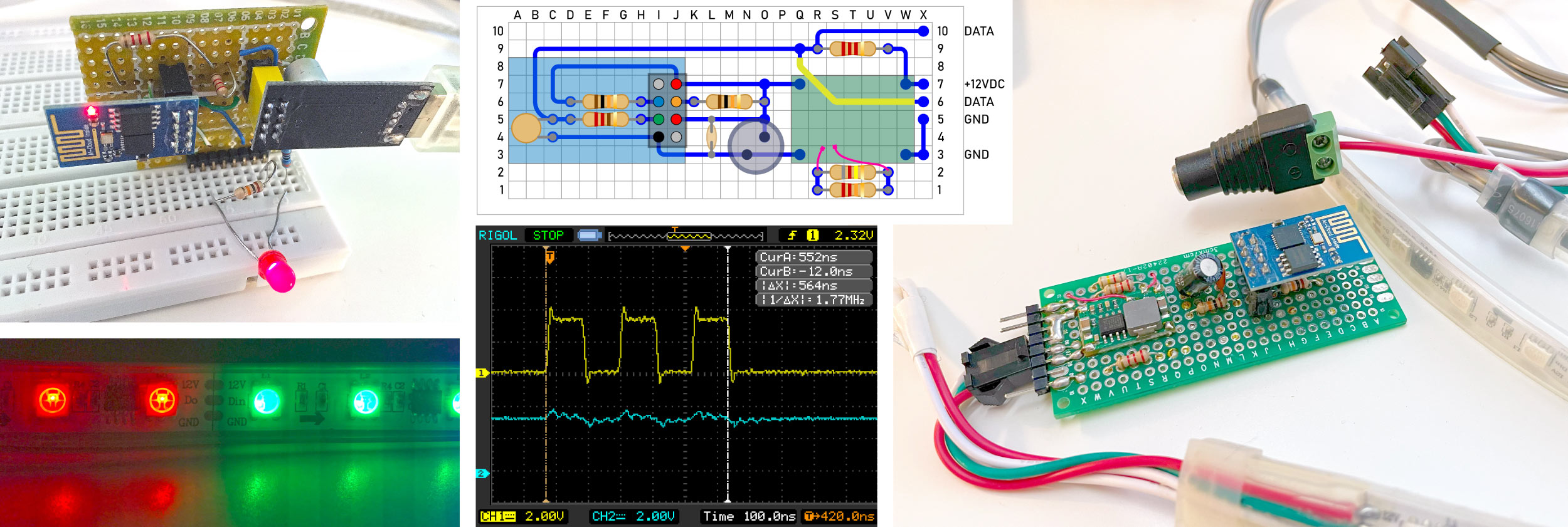
My first full ESP8266-based project used an ESP-01 module and native C firmware (with some inline assembly) to precisely drive a string of WS2812 (actually WS2811) LEDs.
Commands could be sent to the ESP-01 module over wifi (via UDP) to set the RGB colour of individual LEDs, or batches of them.
An app that I wrote natively for both for iOS and Android provided a UI for selecting colours and 'painting' them into cubes of an IKEA Kallax 5x5 shelving unit.
¶2017: ESP8266 non-OS SDK YouTube video
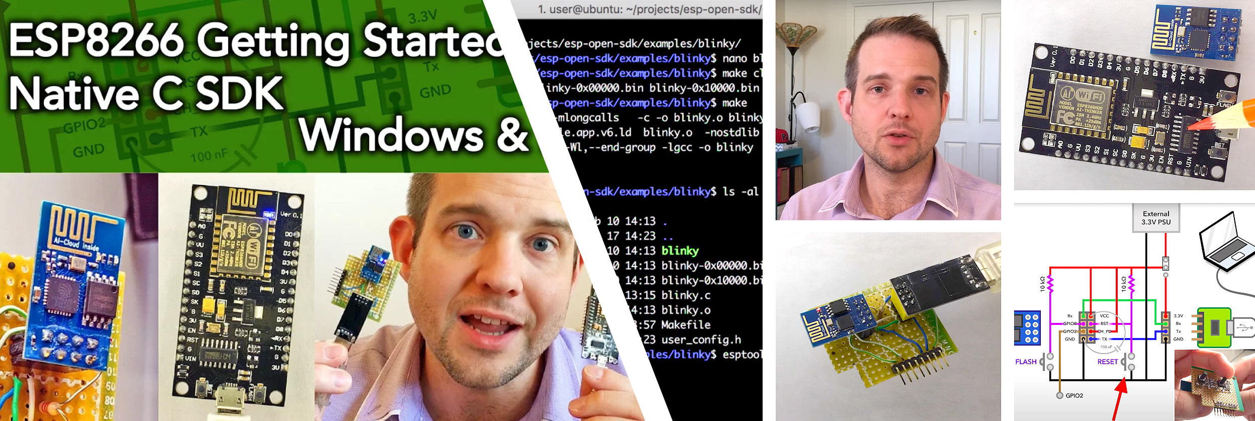
I created a popular YouTube video providing a guide on getting started with various ESP8266 wifi microcontroller modules.
After some early experimentation with the ESP8266 in 2016, I wanted to know how to write native firmware for the device using the official Espressif "Non-OS" C SDK instead of the common Arduino wrapper.
Having gone into some depth while learning the process I put together a 26-minute video explaining how to do this from scratch. In the video I covered:
- An overview of what various ESP modules comprise, and some of their features.
- Using Linux as a development environment, including as a VM under macOS and Windows, then using modules over USB/serial.
- Installing the SDK, building example firmware code, and uploading it to the module.
- ESP-01 specific hardware/requirements.
¶2014: Label printer hacking

I had a cheap Brother P-Touch PT1010 handheld label printer, and -- mostly as a reverse engineering/hacking exercise -- I wanted to convert it for remote control and for printing arbitrary graphics.
After analysing how it controls the thermal print head and other signals from its own internal MCU, I used an ATtiny13 to piggy-back off the existing hardware and succeeded in putting it under PC control with some additional software I wrote.
During the development of this I also wrote a package for both analysing and declaring timing with its own domain-specific language, and which could be used to synthesise timing in code as well as create pretty/annotated timing diagrams (similar to WaveDrom).
The repo for this is ptouch-avr. My journal is all in a paper notebook. Maybe I'll digitise it someday.
¶2012: PIC MCU-based PAL video generator

I always wanted to build a device to generate a video image. I first did this by using a tiny PIC micro. It used its own internal trimmed 4MHz RC clock, generating a PAL composite signal with 4 'levels' (3 tones, plus sync) and a colour burst injected by a separate analog circuit.
¶2012: USB audio device
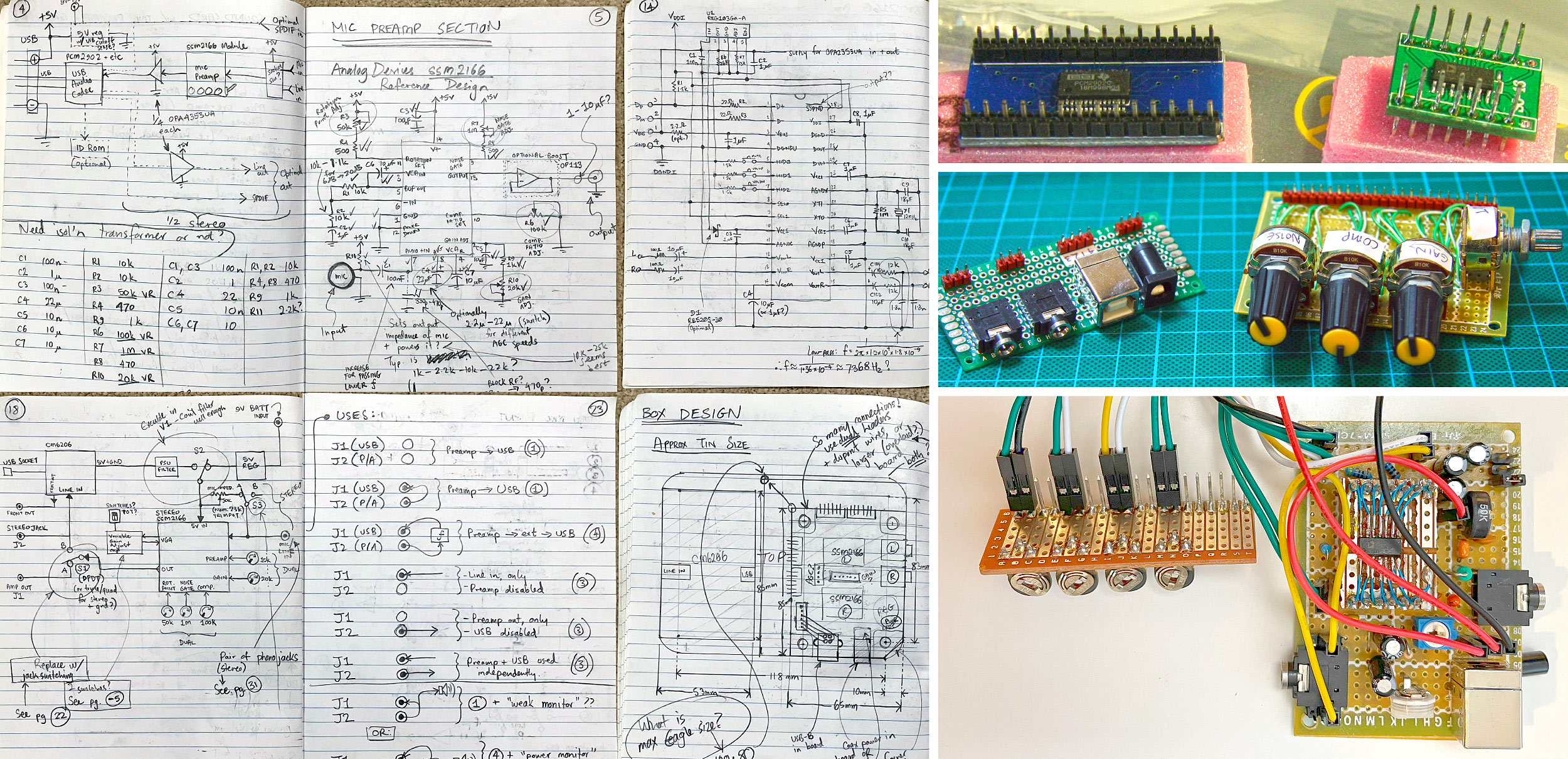
To help a friend who was getting into amateur music recording (voice and acoustic/electric guitar), I dabbled with creating a USB-based sound card with the aim of supporting multiple distinct audio channels and different modes. My prototype used the SSM2166 as preamps with variable/automatic gain and compression and a PCM2902 as a stereo USB audio CODEC.
¶2012: Stereo microphone preamp
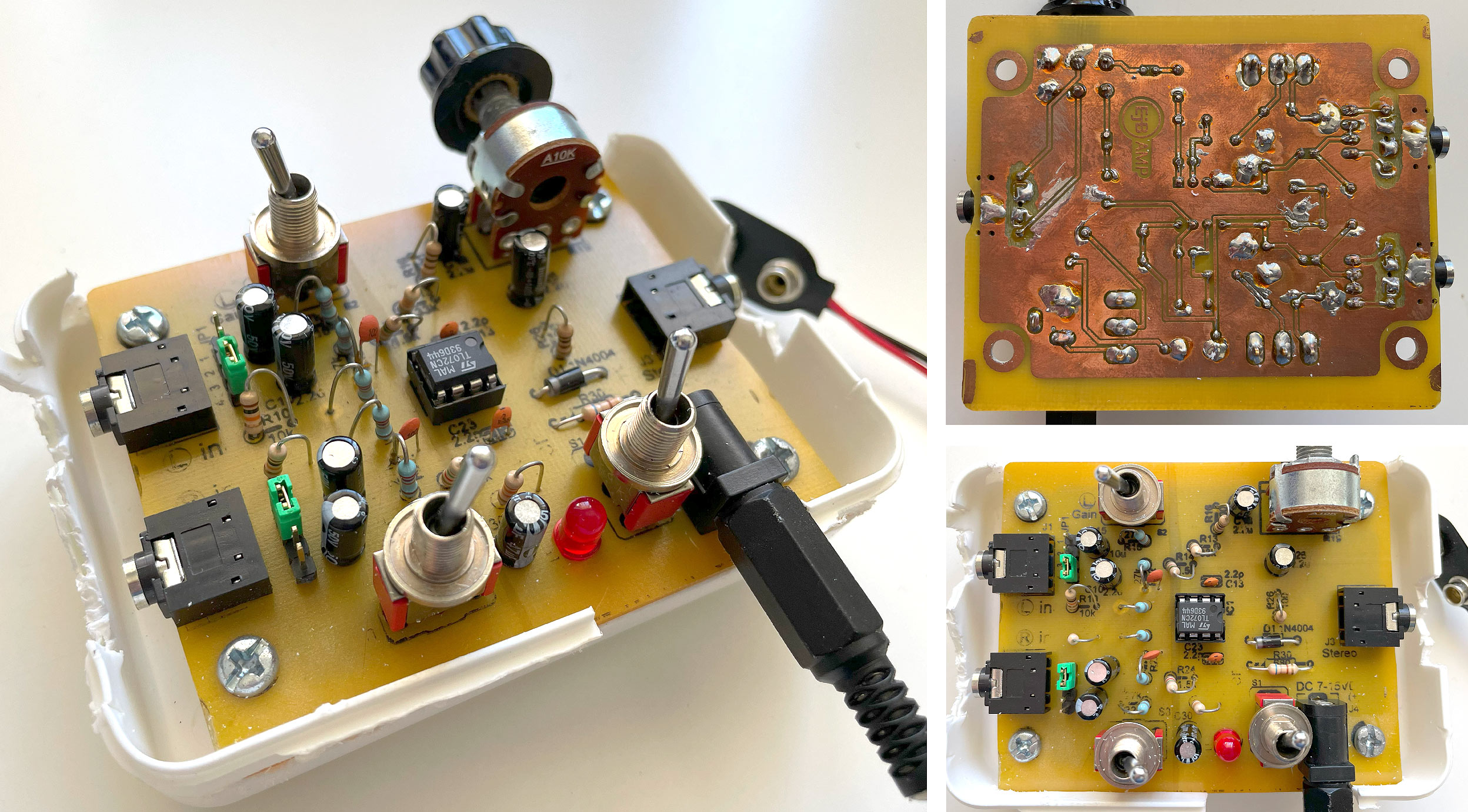
I needed a cheap and basic stereo preamp that could be used with electret microphones or line input, so I built one using the good ol' TL072 dual OpAmp. For this project I designed the PCB in Eagle and used the 'toner transfer method' both for the etch mask and 'silkscreen'.
¶2011: Home PCB etching
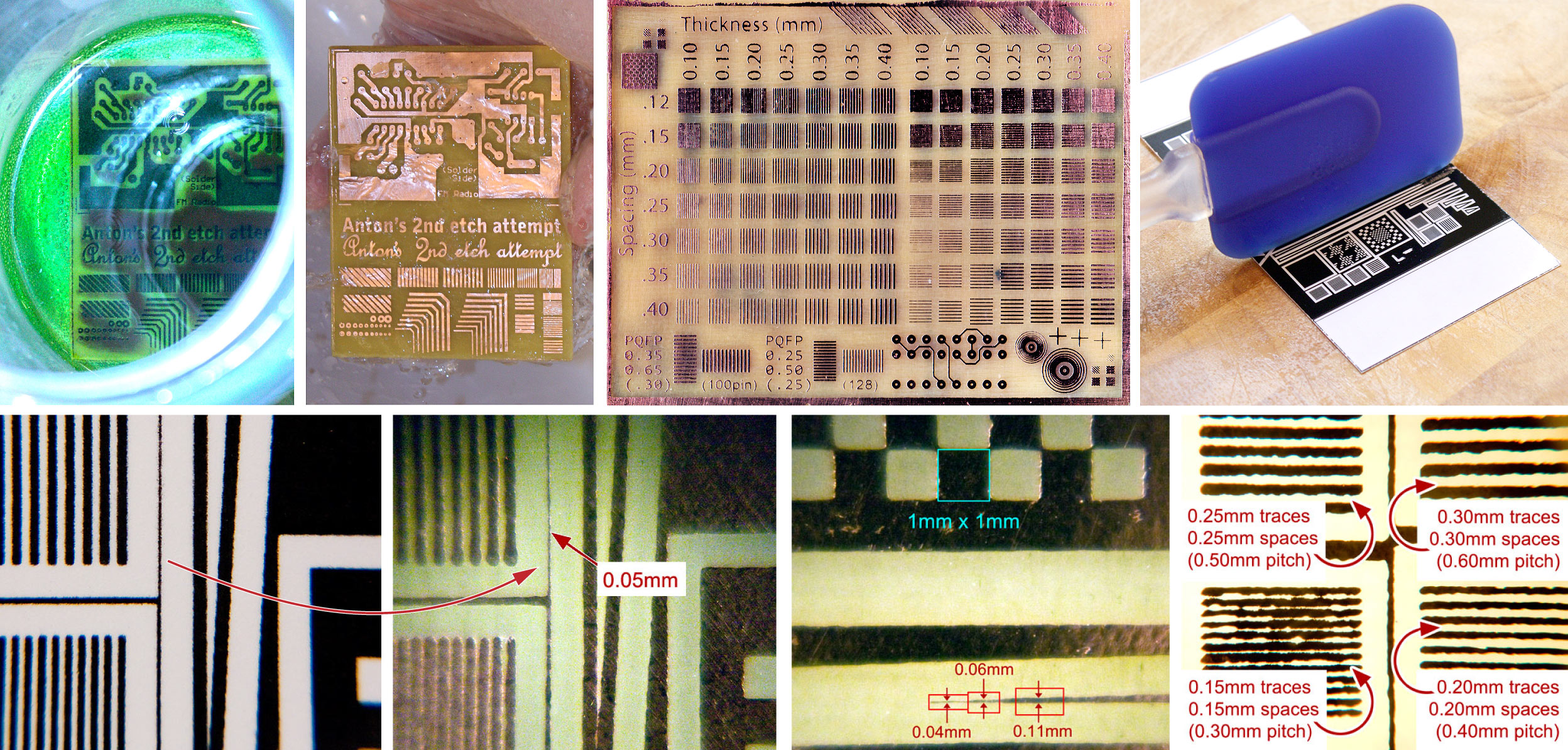
Prior to this I hadn't really done home PCB etching since I was a kid, when I was using a "Dalo" pen and ferric chloride.
I did some experiments and got pretty good results, using a few tricks with the 'toner transfer method', i.e. laser printer images heat-pressed onto copper. After a few attempts, my finest consistently reliable resolution was about 0.2mm, i.e. 0.2mm traces and 0.2mm spaces, suitable for 0.4mm pitch.
I tried:
- Hydrogen peroxide, with cupric chloride vs. hydrochloric acid.
- Iron vs. hot laminator pressing.
- Plain vs. glossy vs. inkjet photo paper.
- Plain black toner vs. 'composite' toner (i.e. heavy density C, M, Y, and K)
I ended up with an approach that used simple black toner on cheap glossy photo paper, sprayed with limonene (which acts as a solvent for the toner). This seemed to make the toner stick well to the copper, and even embed itself in the thin (porous?) glossy coating of the photo paper, such that when it was cool and peeled off, the toner would cleanly pull away a layer of the coating.
I modified a laminator (for higher temp and adjusted roller spacing) for doing the transfer -- it delivers good even pressure and requires less effort.
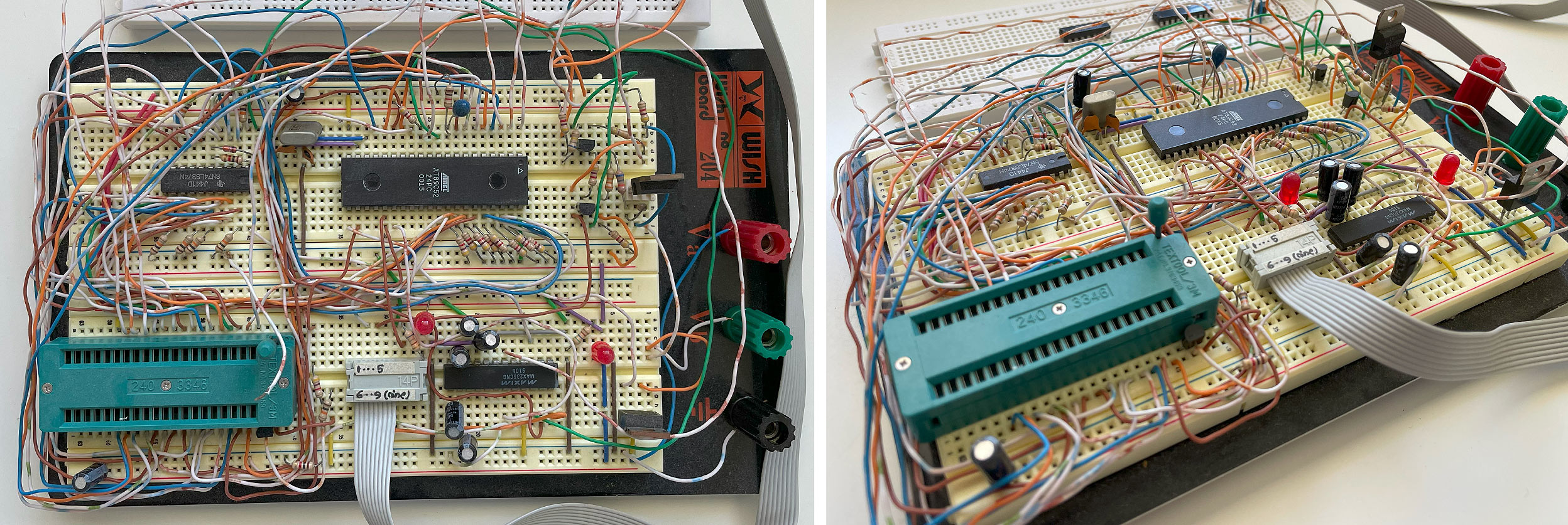
¶2003: 8051 MCU-based 'computer'
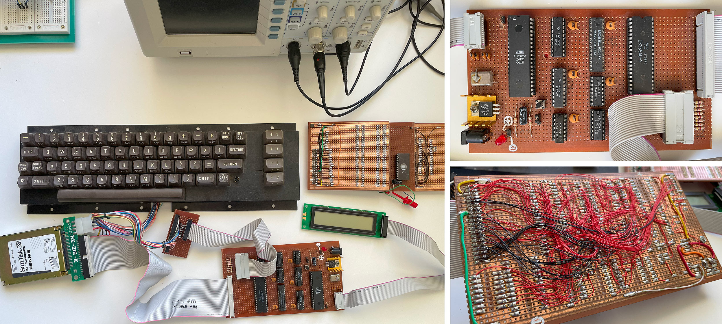
After I got into Intel 8051 assembly language and microcontrollers, I attempted to create a project that was part 'computer', part multi-tool, for digital electronics hacking.
Features:
- Matrix-scan keyboard
- HD44780 LCD display
- 32kB SRAM
- Option to run firmware from internal flash or external memory
- Parallel ATA (IDE) hard drive interface
- UART
- 2nd 8255 PPI as a port expander for GPIOs
¶2002: Flash ROM reader/writer device
I wanted to try making a simple computer based on an old CPU (e.g. Z80 or 6502), and so I needed a way to write ROMs. For both the learning experience, and to save money, I made an EPROM and EEPROM reader and writer.
In order to try making it generic enough to handle different target devices and also to simplify the interface, I used an 8051-based MCU. Control was via an RS232-based PC terminal interface, with firmware that made it easy to switch between reading and writing. It also supported delivering a higher voltage for older devices that needed it for writing and for device ID modes.